Silver Ticket 3 1/4" Fixed Frame Installation
Assemble and Install a 6-Piece Silver Ticket Products fixed frame projection screen.
Introduction
Use this guide to completely assemble and install your Silver Ticket fixed frame screen.- Difficulty: Intermediate
- Time Required: 60 min
- Recommended Labor: 2
Tools
- 1 x Phillips Screwdriver* (not included)
Parts
- 1 x Screen Material
- 2 x Side Frame Rail [S] 45° cuts on both ends
- 2 x Upper/Lower Frame Rail [R1] 45° cut on one end
- 2 x Upper/Lower Frame Rail [R2] 45° cut on one end
- 2 x Aluminum Joint Bar
- 2 x Side Tension Rod
- 4 x Upper/Lower Tension Rod
- 1 x Vertical Support Brace Some models contain two braces
Hardware Kit Includes:
- Springs amount varies
- 2 x Spring Hooks
- 4 x Corner Brackets
- 2 x Lower Mounting Brackets
- 2 x Upper Mounting Brackets
- 17 x Corner Screws
- 8 x Joint Screws
- 8 x Wall Screws
- 8 x Wall Anchors
Steps
1. Preparation
Tip: Be sure to read the included instruction manual and follow the steps it provides along with this step-by-step guide.
Note: Parts and packaging may vary from the photographs shown, depending on the specific screen model.
Warning: If you are unable to safely install the screen, consult a professional.
1. Ensure that the assembly area is clean and clear of debris and sharp objects.
2. Remove all the parts from the packaging box.
3. Verify that all the parts necessary to begin the assembly are present.

2. Splice the Upper and Lower Frame Rails


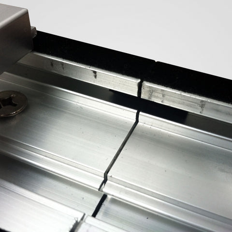
1. Line up the non-angled frame ends of the two lower frame pieces with the aluminum bar in the middle.
2. Secure the aluminum bar to one frame piece with two screws, then slide the other frame piece onto the aluminum bar and secure with two screws.
3. Repeat these steps for the two upper frame pieces.
3. Assemble the Frame


1. Lay out all of the frame pieces in the shape of the finished screen.
2. Insert one end of an L-bracket into the track on one corner angle frame rail and align the mounting holes.
3. Secure the L-bracket to the frame piece with two screws.
4. Insert the other end of the L-bracket into the track on the other corner angle frame rail and align the mounting holes.
5. Completely secure the L-bracket in place with the remaining two screws.
4. Prepare the Screen Material


Note: Each upper/lower tension rod only has one rubber cap - the capped ends of each rod should face out toward the screen corners which will allow the non-capped ends to overlap inside the screen pocket.
1. Unroll the screen material and lay inside the assembled frame with the viewing surface facing downward.
2. Identify the proper-sized tensioning rods for each frame rail and set them near the assembled frame.
3. Carefully slide each tensioning rod into each screen pocket.
4. The short tensioning rods will overlap slightly in the upper pocket and lower pocket.
Warning: Do not force the rod as it may exit the pocket and puncture or scratch the viewing area of the screen.
5. Attach the Screen to the Frame


1. Count the number of cut-outs on each edge of the material and lay out that number of springs at the corresponding side of the frame.
2. Start at the center of the material on each side of the frame and stretch a spring from the frame to the tension rod, securing it to the tension rod.
Note: Each cut-out on the screen material corresponds to one spring that needs to be secured to the frame.
3. Once the center of each side of the material is secured to the frame, work your way outward toward each corner, securing the material to the frame with springs along the way.
4. Once finished, the screen material should be tight all around.
Tip: The screen material is very stretchy and requires a fair amount of tension to stretch the springs. If you are experiencing difficulty, carefully use the spring tensioning tool to pull each spring to the proper position.
6. Install the Vertical Support Brace
FOR DETAILED INSTRUCTIONS, CHECK OUT THIS ARTICLE

Note: The apperance and quantity of vertical support braces will vary between screen models, but the function remains the same.
Note: The support bar fits into grooves on the back of the assembled top and bottom frame pieces. When properly installed, it will provide additional support to the frame between the top and bottom sections to prevent the frame from sagging.
Tip: It may be best to have assistance at this step - one person can pull outward on the frame to make it easier for the other person to slide the bar in place. See the video tutorials in this image gallery of this step for additional information. The support bar fits very tight and may require undoing one or two snap lugs on the material to slide the bar in place. Once the bar is secured, the material can be reattached over the snap lugs.
Warning: If you are having difficulty getting the support bar to slide in place, do not use excessive force as you could damage the screen material.
1. To begin installing the support bar, insert one end of the bar into the groove on one side, then swing the other end toward one side of the frame far enough that the bar is able to slide into the track.
2. Be sure one end of the support is in the groove on one end.
3. Carefully slide the other end of the support bar along the track of the frame until it is straight over the joints of the upper and lower frame pieces.
7. Install the Upper Mounting Brackets


1. Measure the height of the assembled frame (A) and the width of the assembled frame (B). Make note of these measurements.
2. The approximate horizontal bracket spacing (C) can be determined by subtracting 40" (1000mm) from (B). For wood-framed walls, find two studs that are the closest to (C) distance apart, mark these studs - this will be your new horizontal bracket spacing (C).
3. Secure the upper brackets into the wall at the marked locations, level with each other and (C) distance apart. The top of each upper bracket should be 1/4" below the desired location for the top of the frame.
Tip: If the screen is 110" wide (B), subtract 40" to get the bracket spacing of 70". Then find two studs about 70" spaced apart - for 16" spaced studs this would be 64". 64" will be the new horizontal bracket spacing (C).
Note: The minimum ceiling clearance this bracket system will allow is 1/8", which means that the top of the upper brackets needs to be placed at minimum of 3/8" from the ceiling to allow room to mount the screen.
8. Install the Lower Mounting Brackets

1. The bottom of each lower mounting bracket should be (A) minus 1/8" (3mm) below the top of the upper mounting bracket. Mark this location for both lower mounting brackets.
2. Secure the lower mounting brackets into the wall, level with each other, directly below the upper mounting brackets, and (C) distance apart.
9. Install the Assembled Screen

1. Partially loosen the locking screw on each lower mounting bracket.
2. Lift the screen up and rest the screen on the two upper mounting brackets. Make sure the lip of each bracket inserts into the upper mounting track on the upper frame rail.
3. Let the screen hang, resting against the lower mounting brackets.
4. Slide the screen left or right until the desired horizontal position is achieved.
5. Tighten the locking screws on each lower mounting bracket until the frame is secured in place.